
“...the highlight of this pedal is a unique blown amp feature which provides crackles, compression, gating and eq changes similar to that of a tube amp pushed past it’s (sic) limits...”
The Smallsound/Bigsound F- Overdrive has been on the market for some time, and alongside its amazing overdrive pedal, is a highly unique feature: A Crackle/Burst/Threshold system that is an enveloper follower circuit based on the Dr. Quack schematic. The Dr. Quack is an off-shoot of the Dr. Q by Electro-Harmonix. The Dr. Quack was used by The Tone God to create The Punisher, and the Punisher is widely said to be the schematic behind the F- Overdrive’s Crackle/Burst/Threshold (CBT) feature.
“The Punisher is a dynamic power supply sag simulator. The Punisher is not an audio effect but a companion effect that is to be used to control another effect to provide new sounds. You plug your audio signal and power supply into Punisher in series and connect the output audio signal and power supply into the effect to be controlled.”
The envelope follower feeds a control voltage to a JFET, which in turn alters its resistance, producing a voltage-controlled resistor in the process. The JFET is run in series with the power supply to a JFET stage, thus mis-biasing the JFET stage in the process. The resulting sounds is said to emulate that of an amp on the verge of explosion whose tubes wax and wane.
For further reading, I suggest visiting this page and scrolling down to “Driving Effects Circuits with the LFO Waveforms.”
Having built the Smallsound/Bigsound (SSBS) Mini, I started to set my eyes on the SSBS F- Oveddrive. However, I had little clue as to the underworkings of the CBT. Initially I thought the circuit was some sort of phaser/tremolo circuit that altered the volume/output of a specific stage of the SSBS Mini. But I wasn't too sure. Also, pictures of the F- Overdrive PCB did not look anything like a tremolo/phaser circuit. Although, oddly enough, the concepts of JFETs as voltage-controlled resistors (VCRs) is closely associated with phasers.
I began researching the most readily available information out there: It's a voltage-controlled envelope follower circuit. I pulled up schematics for the Glowfly Retroflect and Frantone Vibutron, which features envelope followers affecting FETs. I shot off a few Google searches, which immediately turned up the Dr. Q schematic. Unfortunately, there was very little information about how that particular circuit fit in the CBT. I wish I could say that the subsequent research was streamlined once I aligned the CBT circuit with the Dr. Q schematic, but in reality, I spent quite a few days perusing various forums to no avail. A culmination of 2-3 days of digging deep into forums helped me learn that the envelope follower controlled a "resistor," the resistor was associated with the second stage of the SSBS Mini, and the overall result was the JFET being mis-biased.
Simple enough, right?
A few more hours of Google searching lead me to Reddit where someone used the keywords, "dynamic sag." (Coincidently, I had just completed a LM317-based sag unit.) A few more Google searches lead me to the Pusnisher circuit. Furthermore, if you Google the Punisher circuit, the CBT pops-up alongside it!
I breadboarded the circuit, but I could not get it to function. Furthermore, I found several posts of individuals identifying the Punisher as being a key part of the CBT, but only a handful of people who successfully implemented the circuit: The Tone God, author of the circuit; some random guy on DIYStompboxes; and the mind behind SSBS. After a day of troubleshooting the circuit, I crowdsourced Reddit and DIYStompboxes for assistance.
The key piece missing from the original schematic was just a pair of resistors: The op-amp was not biased! The addition of the transistors allowed the circuit to work. I also experimented/ with and implemented some other changes from forum suggestions and the Dr. Q, which allowed the envelope signal to be much stronger. However, one change that helped was found on accident: I was trying out different biasing resistors and left one resistor in. This made the circuit work much better for reasons I am unsure of.
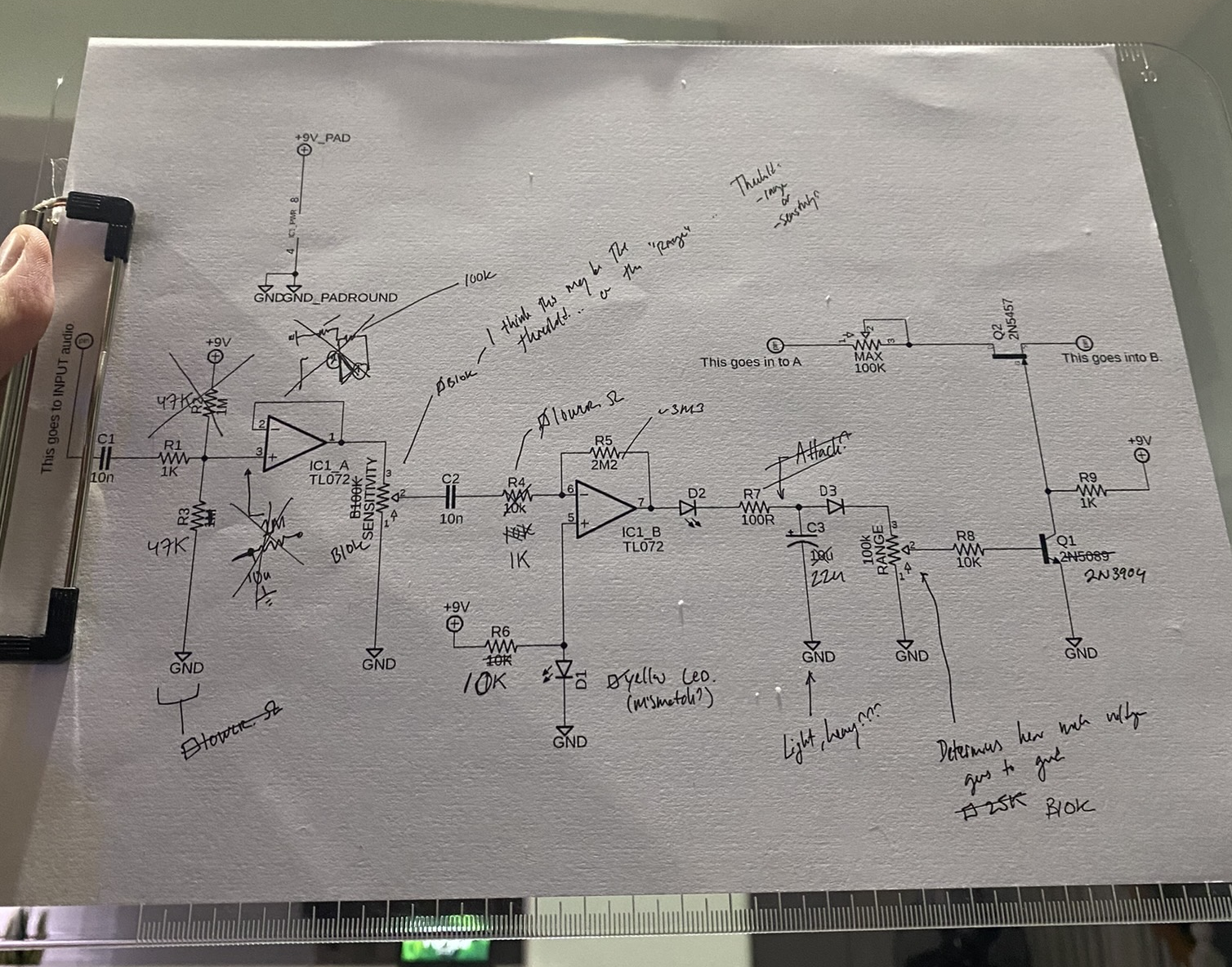
Schematic with many changes.
And like that, I figured it all out...sort of.
See, I call this "Progress Report" because there are still a few of issues to solve:
How to calculate the resistance that is bestowed upon by the VCR/JFET.
How to make the circuit smoother as the attack/release is really fast.
How to elicit more crackling. I actually did manage to do this when I was using two 1M ohm resistors for biasing, but the envelope signal was not as strong.
What the “Heavy/Light” function changes. I think it either changes the electrolytic capacitor attached to red LED or it may be the Attack function seen in the Nurse Quacky.
As for now, this is it.

Left side is the Crackle/Burst/Threshold function. On the right is a dummy unit to test the circuit. The dummy unit based on the Fairfield Circuitry Barbershop, which is like a minimalist SSBS Mini.
Updates:
May 8, 2023: Grammar and spelling errors corrected.