I originally posted two similar versions of this blog on Reddit and the PedalPCB forum. This version includes changes based on feedback from those posts.
Summary
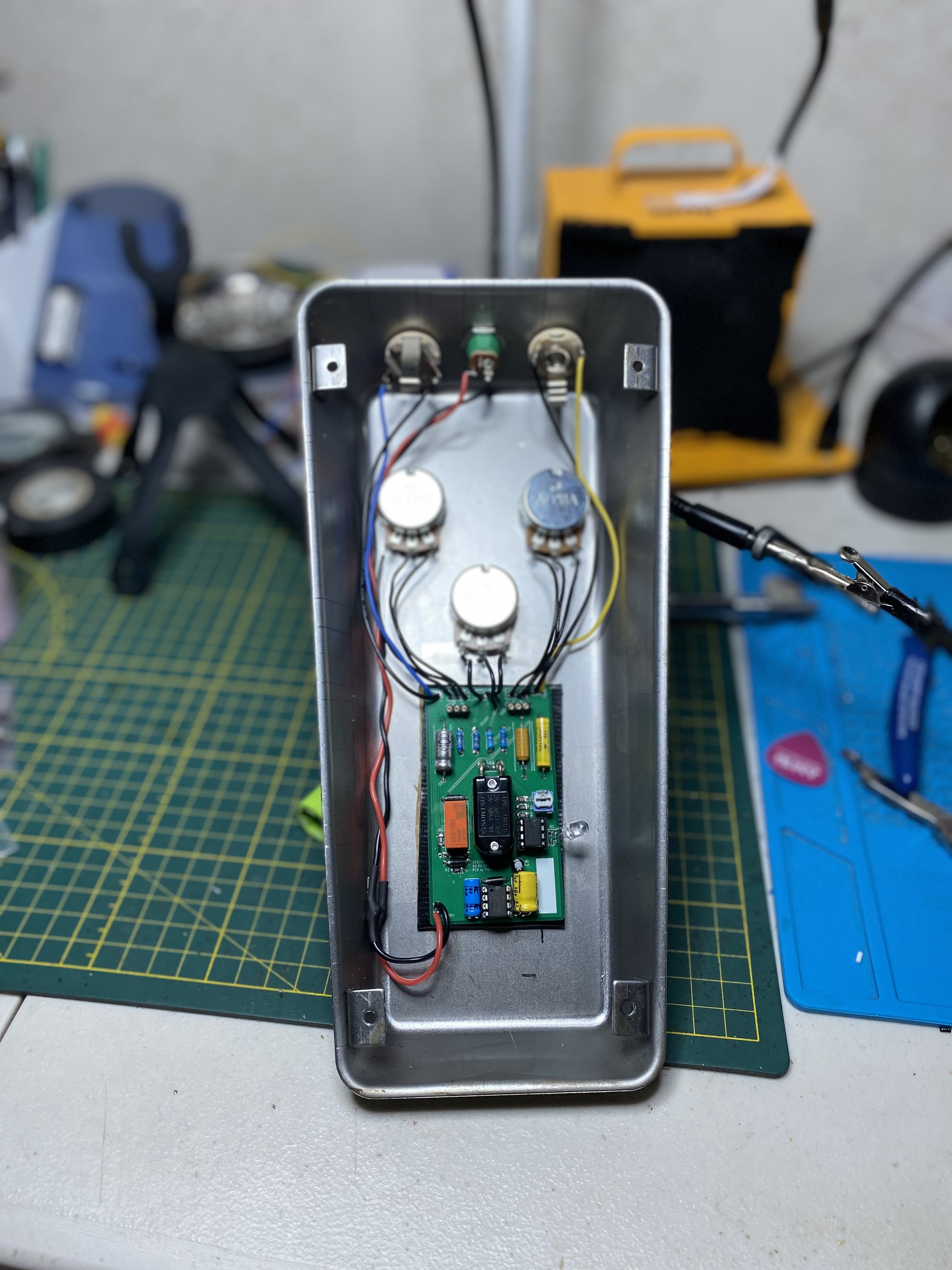
I spent the past few months figuring out the dynamic sag portion of the Smallsound/Bigsound (SSBS) F- Overdrive, had a breakthrough, and then stuck it into a Fairfield Circuitry Barbershop + SSBS Mini-hybrid drive.
The companion effect, an envelope-controlled voltage starve circuit, mimics a dying tube amp and responds to an individual's playing: As described by Brian/SSBS, the dynamic sag circuit is “dynamically modulated (envelope controlled)…turn up the threshold and the harder you play, the more the overdrive crackles, tries to keep up… and fails miserably.” I call it a practice in kintsugi - or discovering and embracing the musicality in the “brokenness” of the pedal.
In this post I have included video demos, a schematic of the dynamic sag circuit, background information, a schematic of the dynamic sag circuit in practice, and final notes on shortcomings and future things to explore.
The post is quite lengthy, so I implemented headers in case you want to jump ahead to a specific section. Also, instead of posting ongoing updates or progress reports, I will just update this post.
(Last updated: 7-4-2023)
Video Demos
Background
A few months ago, after having built a SSBS Mini clone, I came across a video demo of the F Overdrive. The video detailed a feature within the pedal that was described as an envelope follower that starved a single gain stage. I thought the process would be as simple as a Google search, but whenever I did, I found threads suggesting people just Google the answer which leads to more threads suggesting people just Google the answer which leads to more threads…so on and so forth. In all my hours of Googling and perusing forums like FreeStompBoxes and DIYStompBoxes, I had only found one person who figured out the circuit and produced a functional dynamic sag circuit: Brian from SSBS.
Eventually I happened across a thread on Reddit in which someone used the phrase “dynamic sag,” which lead me to the Tone God Punisher circuit.
The Tone God Punisher circuit is not so much a pedal as a companion piece for a pedal. Utilizing an envelope filter, a NPN BJT, and a JFET, the circuit starves current and mimics a dying tube amp. The core concept of the circuit (envelope follower and voltage controlled resistors) can be used for a myriad of applications in which an input signal dynamically controls another part of the pedal - be it, gain, volume, delay time (like the Retroflect), clipping, etc.
The circuit itself is derived from the Nurse Quacky, which in turn is derived from the Dr. Quack, which in turn is based on the EHX Doctor Q.
The dynamic sag feature is a hallmark of the SSBS F Overdrive. More recently The Shields Blender sported a similar feature. Fender ostensibly claims the dynamic sag - or “reactive sag” is “the first of its kind,” but clearly it isn’t, lending credence to the fact that Brian/SSBS is (was?) quite ahead of his time. To clarify, I don’t know if the sag circuitry in the Shields Blender is the same as the SSBS, but I do take issue that the reactive sag is being purported as being revolutionary when another pedal had the same function years prior.
Research
To say it took me a couple of months to figure out how to get the dynamic sag circuit to work would be an understatement. The original Tone God Punisher schematic was not functional. Through a series of trial, error, soliciting advice, multiple breadboards layouts, meticulously looking at internal of the SSBS OD and unpopulated SSBS OD PCBs, and a random late night epiphany, I managed to get the circuit working.
The big changes I had to implement were (1) the biasing of the op amp and (2) the removal of the JFET. The latter was a last minute decision brought about by a FreeStompBoxes.Com post in which a user felt the JFET and BJT interaction would be too unpredictable and warrant careful (laborious) selection of components. Alas, I got the circuit working and stuck it into a Fairfield Circuitry Barbershop/SSBS Mini hybrid.
Because of the alterations I have made and lack of the heavy/light control in my circuit, I have to state that this is not 100% a replication of the dynamic sag circuit in the SSBS OD; however, it is very similar in topology and produces the same effect.
Schematic of the Dynamic Sag

Note: Since originally sharing this schematic, I have made some changes based on feedback I received. The above schematic also includes a few proposed changes that I have learned about since my initial postings on the forums.
Practical Application in a Pedal Schematic

Based on my analysis of the SSBS Overdrive PCB, my circuit is probably only 80% similar to what's in the SSBS Overdrive - but I do believe it is a fair approximation.Above is a schematic of the Fairfield Circuitry Barbershop with the implementation of the dynamic sag unit. Note this is not the same schematic as the demo videos. I just wanted to share how the schematic would look once all the pieces are put together.
Explanation
(Note that parts referred to in this section is referring to the primary Dynamic Sag Circuit schematic.)
The input of the guitar signal splits off into the actual audio circuit and into the dynamic sag circuit. The signal goes through a buffer into the Sensitivity control. Thereafter, the signal goes to an envelope follower, which is a oddly-biased op amp. The envelope follower triggers an LED. LED charges up a capacitor, which in turn discharges to the BJT and allows current/power to flow to ground. The current/power that flows to ground is current/power that’s meant for the gain stage, effectively starving the stage in the process. LEDs’ forward voltage must be matched. Vout goes to the power source of the gain stage and R10 is whatever the bias resistor is.
The two knobs, Sensitivity and Threshold, control circuit. Sensitivity should be adjusted based on playing style - eg. Picking/strumming strength and Threshold determines how much starve should occur. Mark Hammer proposed that the RC network could be changed in order to increase/decrease the decay or even make the effect less aggressive overall. I postulate that the SSBS Fuck’s compression switch (heavy/low) goes between two different RC networks (R8, C4). In my own personal builds, I usually make C4 10uF. I find that values greater than 22uF drain too much power and take longer for the circuit to recover. Another proposal is to replace R8 with a potentiometer in series with a 50-100 ohm resistor in order to make an Attack control. The two foot switches are Bypass and Dynamic Sag. Bypass activates the drive and Dynamic Sag activates the Dynamic Sag.
The schematic for the dynamic sag footswitch bypass wiring is shared in the schematic under "Pedal Schematic or Practical Application." This will enable you to toggle the dynamic sag on or off. You can also opt for a monetary DPDT switch so that pressing/holding activates the sag and releasing immediately turns it off.
Shortcomings and Proposed Changes
Based on my analysis of the SSBS Overdrive PCB, my circuit is probably only 80% similar to what's in the SSBS Overdrive - but I do believe it is a fair approximation. In the future I would like to find a better way to control the rate of voltage change. I think a slew rate limiter is a plausible solution.
Updates
July 4, 2023
When my Skeptical Buffer schematic came under criticism - which I invite for the sake of correcting my work, I decided to proceed with using Simulation Program with Integrated Circuit Emphasis (SPICE). The program I chose was EveryCircuit. I plugged in the Dynamic Sag circuit and experimented with the different suggestions I posted in my original schematic. To my surprise, none of what I proposed did much. The one change that produced the most change - a more subdued voltage starve - was increasing R9, the resistor from Threshold to the base of the BJT.
Furthermore, as a result of this change, I am inclined to believe that the Compression switch on the SSBS overdrive toggles between two different resistors. The larger the value of R9, the higher the minimum voltage will be when the gain stage starves, and the smaller the value of R9, the lower the minimum voltage will be. Also in future builds, I have considered either omitting the Sensitivity control or making it an internal trimmer because I find that if you can fine tune R9, the circuit may not need a sensitivity knob and the Threshold control will offer more usability.
September 22, 2023
Dino from DEAD END FX has stated that their company plans to release a SSBS F*ck PCB. He has offered the following insight as to my research/development:
Theoretically, there is nothing wrong with the TG (Tone God) schemo. It really depends on the application, as well as the gain structure of what you want to influence with it. Where the F*ck is concerned, there is no Vref scheme in the power structure at all, meaning that the opamp input is not biased, and it works fine. Even with a guitar signal. The sag structure is more or less verbatim to the TG schemo, EXCEPT... there is one resistor to ground added at the back end of the envelope. You're not influencing the main rail voltage here, but rather, the bias voltage of one JFET within the audio gain structure. As such, minor (and I mean MINOR) tweaking might be required to get it to work with the destined application. From my breadboarding, I find that the resistor acts as a bleed control of the sag function (biasing the base of the NPN transistor). My experimenting led me to replace the resistor with a pot, which enhances the sag depending on the gain structure of the circuit being influenced, which is important. I found the F*ck that I had to lack sufficient "fade, crackle, pop" when the gain was turned up high, which using a pot instead of a fixed resistor value (as previously mentioned), helps compensate for.
As for the F*ck, I can tell you from experimentation that even the type of JFET's used as the VCR is important. The 2N5457's gave the smoothest voltage transitions, while others (ex.PF5102) were much more abrupt. At the initial attack, the bias voltage of the JFET used in the audio gain side of the circuit can drop from it's normal 4.5v to less than 1v when being "sagged", adequately providing the "edge of tube disaster" effect that is sought after.